In the current structure and designs of buildings like banks, gas stations, and offices, a fire alarm is a basic necessity. They identify the fire in the surrounding at the beginning stage by detecting smoke or warmth and raise an alert which cautions individuals about the fire and furnish adequate time to take precautionary measures. It is not only the cause to prevent big looses to occur but some times it saves many lives just by detecting the fire and alerting the people in the surrounding just by sounding an alarm. In this article, we will study the method to built a simple fire alarm by using a 555 Timer IC. It will detect the fire and sound a buzzer.

Fire Alarm Circuit
A thermistor is the heart of this circuit. This sensor will be used to detect the fire. It is a resistor that is very sensitive to temperature. This means that a small change in temperature will cause a large change in its internal resistance. Its resistance is inversely proportional to the temperature. It means that if the temperature increases, the resistance will decrease and when the temperature decreases, the resistance will increase. An NPN transistor is used as a switch in this circuit.
How To Design A Fire Alarm Circuit?
Now, as we know the main abstract of this project, let us move a step ahead and gather some more information like a component list and working of the circuit, to make the final product.
Step 1: Collecting The Components
The best approach to start any project is to make a list of components and going through a brief study of these components because no one will want to stick in the middle of a project just because of a missing component. A list of components that we are going to use in this project is given below:
- NE555 timer IC
- BC-547 Transistor
- No products found.
- No products found.
- 100k-ohm Resistor
- 4.7k-ohm Resistor
- No products found.
- 1uF Capacitor
- No products found.
- No products found.
- Connecting wires
- 9V Battery
Step 2: Working Of The Circuit
Pin1 of the 555 Timer IC is the ground Pin. Pin2 of the timer IC is the trigger pin. the second pin of the Timer IC is known as the Trigger Pin. If this pin is directly connected to pin6, it will work in Astable mode. When the voltage at this pin drops below one-third of the total input, it will get triggered. Pin3 of the timer IC is the pin where the output is sent. Pin4 of the 555 Timer Ic is used for the reset purpose. It is initially connected to the positive terminal of the battery. Pin5 of the timer IC is the control pin and it does not have much use. In most of the cases, it is connected to the ground through a ceramic capacitor. Pin6 of the timer IC is named as the threshold pin. pin2 and pin6 are shorted and are connected to pin7 to make it operate in Astable mode. When the voltage of this pin gets greater than two-third of the mains voltage supply, the Timer IC will come back to its stable state. Pin7 of the Timer IC is used for the discharge purpose. The capacitor is given the discharge path through this pin. Pin8 of the timer Ic is directly connected to the ground.
Here, the 555 Timer IC is used in Astable mode. In this mode, an oscillating sound will be produced by the buzzer. So, as this circuit is working in astable mode, the resistor R1 and R2 are used to charge the capacitor C1. The charging process will continue until the voltage is 2/33 Vcc. Then it will start to discharge through R2, till the voltage reaches 1/3 Vcc. the pulse is generated in a way that, while the capacitor is charging, the output pin3 of the 555 timer IC remains HIGH. This pin goes to the OFF state when this capacitor is discharging. A buzzer is connected to the output pin3 of the 555 Timer IC. The buzzer will produce a beep sound when the outputpin3 is high and will remain silent when the output pin3 will be in the OFF state. The frequency generated at the output pin of the timer IC can be adjusted by setting the value of R1 or C.
Step 3: Assembling The Components
Now, as we know the main connections and also the complete circuit of our project, let us move ahead and start making the hardware of our project. One thing must be kept in mind that the circuit must be compact and the components must be placed so close.
- Take a Veroboard and rub its side with the copper coating with a scraper paper.
- Now Place the components carefully and close enough so that the size of the circuit does not become very big
- Carefully make the connections using solder iron. If any mistake is made while making the connections, try to desolder the connection and solder the connection again properly, but in the end, the connection must be tight.
- Once all the connections are made, carry out a continuity test. In electronics, the continuity test is the checking of an electric circuit to check whether current flow in the desired path (that it is in certainty a total circuit). A continuity test is performed by setting a little voltage (wired in arrangement with a LED or commotion creating part, for example, a piezoelectric speaker) over the picked way.
- If the continuity test passes, it means that the circuit is adequately made as desired. It is now ready to be tested.
- Connect the battery to the circuit.
The circuit diagram of this project is given below:
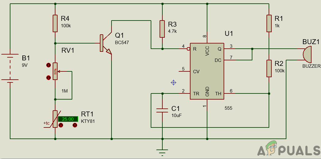
Circuit Diagram
Step 4: Testing
The circuit diagram of this project can be seen in the above section. The thermistor will remain at 10k-ohm when there will be no fire. In this case, as there will be enough voltage across the base-emitter of the transistor, the transistor will remain at ON state. SO, the reset pin of the 555 Timer IC will be connected to the ground because the transistor is in ON state. In this state with the reset pin connected to the ground, the 555 Timer IC will not operate.
Now, when the thermistor is put near the fire. The fire will cause its resistance to decrease. With the decrease in this resistance, the base voltage of the transistor decreases. The transistor will eventually turn OFF when the base voltage decreases its operating voltage. As soon as the transistor goes OFF, the reset pin of the timer IC gets connected to the positive terminal of the battery. As soon as the reset pin goes ON, the buzzer will produce a beep sound.
To turn a transistor ON, a drop of 0.7V is required. So, t make the circuit work according to our wish, we have to adjust the resistance of the potentiometer. So, to adjust this value, first, break the connection of thermistor from the main circuit, and then rotate the knob of the potentiometer. As the potentiometer is grounded at this moment, rotate it until the buzzer sounds. At this point, the buzzer will start producing the beep sound even if a little resistance is lowered. Now connect the thermistor back to its place.
How to Fix “Printer is in an error state” Issue?
- Recognizing the importance of a printer’s duty cycle is crucial for choosing a device that matches your print volume needs. Staying within this limit ensures the printer operates efficiently and prolongs its lifespan, minimizing the risk of maintenance issues.
- Proper humidity, temperature, and cleanliness management can significantly enhance printer performance and maintain its duty cycle, preventing unnecessary wear.
- Enhancing a printer with upgrades like additional memory or better mechanical parts can improve its workload handling and extend its practical duty cycle, boosting overall durability and efficiency.
When choosing a new printer, you might come across the term “ duty cycle ” in the specifications. This guide will explain what a duty cycle is, why it matters, and how it can help you choose the right printer. We’ll keep things simple so you can easily understand how to use this information when shopping for a printer.
- Printer Duty Cycle: What It Means and Why It Matters?
- Why the Duty Cycle Is Key to Choosing the Right Printer?
- Duty Cycle vs. Recommended Monthly Print Volume: What’s the Difference?
- What Happens If You Ignore Printer Duty Cycle Recommendations? ↪ Real-World Scenarios: Why Exceeding the Duty Cycle Can Cost You
Printer Duty Cycle: What It Means and Why It Matters?

What is the meaning of Printer Duty Cycle?
The printer duty cycle represents the upper limit of a printer’s capacity—how many pages it can reliably process in a month before the risk of wear or malfunction increases. This figure is crucial for understanding printer performance limits and ensuring that your chosen printer can handle the expected work volume.
Manufacturers determine a printer’s duty cycle through stress testing, where the printer is pushed to its limit to identify how many pages it can produce each month before malfunctioning. These tests help set a reliable performance gateway for users.
A printer’s duty cycle is like a car’s speedometer—you wouldn’t drive a car at top speed all the time, and you shouldn’t push a printer to its maximum duty cycle. Doing so can lead to quicker wear and tear, more frequent maintenance, and a shorter lifespan.
If you’re unsure whether to choose an inkjet or laser printer, this detailed guide compares both options to help you make an informed decision.
Why the Duty Cycle Is Key to Choosing the Right Printer?

The Importance of Duty Cycle in printer selection
Knowing the duty cycle is essential when choosing a printer, as it determines how well the device can handle your monthly print volume without excessive wear or maintenance.
Here is why the duty cycle matters in printer selection:
- Fit for purpose: Selecting a printer with a suitable duty cycle ensures it can handle your monthly printing volume efficiently, reducing stress on its components.
- Longer lifespan and better performance: Staying within the duty cycle ensures optimal print quality and speed while prolonging the printer’s life, avoiding frequent breakdowns.
- Cost efficiency and reduced downtime: Operating within the duty cycle minimizes the need for repairs and reduces operational disruptions, managing long-term costs.
Duty Cycle vs. Recommended Monthly Print Volume: What’s the Difference?

Duty Cycle vs. recommended monthly print volume
The recommended monthly print volume is the optimal number of pages a printer should handle each month for the best performance and longevity. Unlike the maximum capacity indicated by the duty cycle, this number guides regular usage, ensuring the printer operates efficiently without excessive wear.
If your print volume regularly exceeds the recommended amount but stays within the duty cycle, the printer may operate safely in the short term, but it could still experience accelerated wear and reduced lifespan over time.
In such cases, consider upgrading to a higher-capacity printer or spreading print jobs across multiple devices to ensure long-term performance.
Here are the differences between the duty cycle and recommended monthly print volume:
- Duty cycle: Represents the maximum number of pages a printer can handle in a month without breaking down. It assesses the printer’s upper limit.
- Recommended monthly print volume: Suggests a practical, workable number of pages to print each month to keep the printer in good condition over its lifespan.
What Happens If You Ignore Printer Duty Cycle Recommendations?

Consequences of ignoring Duty Cycle recommendations |AndranikHakobyan via Canva
Ignoring the duty cycle limits poses more severe risks than exceeding the recommended monthly print volume, leading to serious long-term consequences.
While exceeding the recommended volume occasionally may result in additional wear and tear, consistently exceeding the duty cycle can lead to frequent breakdowns, reduced performance, and a shortened lifespan.
Ignoring duty cycle limits leads to frequent breakdowns, reduced performance, and increased maintenance, ultimately shortening the printer’s lifespan and causing more frequent operational downtime and higher repair costs. Long-term, pushing a printer beyond its limits leads to greater financial burdens due to premature replacements and inefficiencies.
↪ Real-World Scenarios: Why Exceeding the Duty Cycle Can Cost You
For example, in a busy law firm, overlooking duty cycle limits during a high-stakes period could cause a printer breakdown just before a critical deadline, delaying crucial legal filings and ultimately compromising client service.
For small businesses, consistently exceeding a printer’s duty cycle can lead to costly emergency repairs or premature equipment replacements, straining financial resources.
