Street crime is very common in the modern century. Everybody needs to feel secure when they are at home either while sleeping at night or during day time. So, many security alarm systems are available in the market. These systems are very efficient but costly. A burglar alarm or an intruder alarm is basically an electronic device that sounds an alarm when it detects an intruder in the home. We can make an intruder alarm circuit at home which will be almost equally efficient for a specific range of distance and will be very low in cost.
Security Alarm
This article is about making an intruder alarm using Arduino and PIR sensor. When the PIR sensor will detect an intruder, it will send a signal to Arduino and the Arduino will sound an alarm. This circuit is very simple and will be designed on a Veroboard. This Veroboard will be installed at that place of the house where there is more danger of an intruder to get inside of the home.
How to design a PIR Sensor based Intruder Alarm?
The best approach to start any project is to make a list of components and going through a brief study of these components because no one will want to stick in the middle of a project just because of a missing component. Let’s make a list of components, purchase them and get started with the project. The Vero Board is preferred for assembling the circuit on hardware because if we assemble the components on breadboard they may detach from it and the circuit will become short hence, Veroboard is preferred.
Step 1: Collecting The Components (Hardware)
- No products found.
- No products found.
- 10k-ohm Resistor
- No products found.
- No products found.
- No products found.
- No products found.
- 9V Battery
- No products found.
- No products found.
- Connecting wires
- Digital Multi Meter
Step 2: Components Needed (Software)
- Proteus 8 Professional (Can be downloaded from Here )
After downloading the Proteus 8 Professional, design the circuit on it. I have included software simulations here so that it may be convenient for beginners to design the circuit and make appropriate connections on the hardware.
Step 3: Working Of The Circuit
The working of this circuit is very simple. At first, the state of the PIR sensor is set to LOW. it means that no motion is detected. When a motion will be detected by the PIR sensor, it will send a signal to the microcontroller. The microcontroller will then switch the buzzer and LED on. If no motion is detected, the LED and buzzer will remain in the off state.
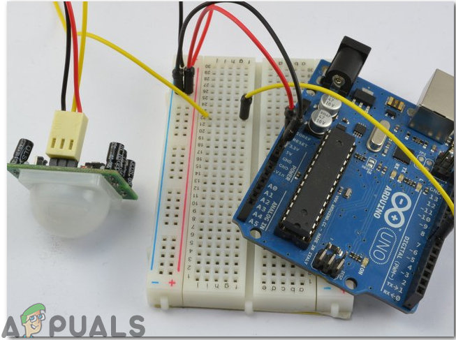
Step 4: Assembling The Components
Now, as we know the main connections and also the complete circuit of our project, let us move ahead and start making the hardware of our project. One thing must be kept in mind that the circuit must be compact and the components must be placed so close.
- Take a Veroboard and rub its side with the copper coating with a scraper paper.
- Now Place the components carefully and close enough so that the size of the circuit does not become very big
- Take two pieces of Female headers and place it on the Veroboard in such a way that the distance between them should be equal to the width of the Arduino nano board. We will later mount the Arduino nano board in these female headers.
- Carefully make the connections using solder iron. If any mistake is made while making the connections, try to desolder the connection and solder the connection again properly, but in the end, the connection must be tight.
- Once all the connections are made, carry out a continuity test. In electronics, the continuity test is the checking of an electric circuit to check whether current flow in the desired path (that it is in certainty a total circuit). A continuity test is performed by setting a little voltage (wired in arrangement with a LED or commotion creating part, for example, a piezoelectric speaker) over the picked way.
- If the continuity test passes, it means that the circuit is adequately made as desired. It is now ready to be tested.
- Connect the battery to the circuit.
Now verify all the connections by looking at the circuit diagram below:
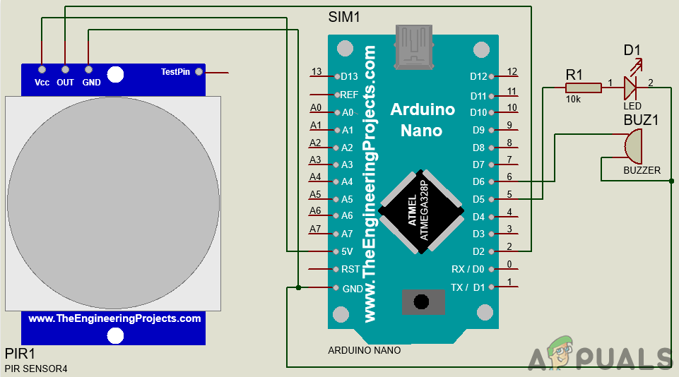
Circuit Diagram
Step 5: Getting Started With Arduino
If you are not already familiar with the Arduino IDE, don’t worry because a step by step procedure to set-up and use Arduino IDE with a microcontroller board is explained below.
- Download the latest version of Arduino IDE from Arduino.
- Connect your Arduino Nano board to your laptop and open the control panel. in the control panel, click on Hardware and Sound . Now click on Devices and Printers. Here, find the port to which your microcontroller board is connected. In my case it is COM14 but it is different on different computers. Finding Port
- Click on the Tool menu. and set the board to Arduino Nano from the drop-down menu. Setting Board
- In the same Tool menu, set the port to the port number that you observed before in the Devices and Printers . Setting Port
- In the same Tool menu, Set the Processor to ATmega328P (Old Bootloader). Processor
- Download the code attached below and paste it into your Arduino IDE. Click on the upload button to burn the code on your microcontroller board. Upload
Step 6: Understanding The Code
The code of this project is quite well commented and very easy to understand. But still, it is briefly explained below.
- At the start, Pins of the Arduino are initialized which will be later connected to the LED and the buzzer. A variable is also declared that will store some values during run time. Then the initial state of the PIR is set to LOW, which means that it is told that no motion is detected initially.
int ledPin = 5;     // choose the pin for the LED
int Buzzer = 6;     // choose the pin for the Buzzer
int inputPin = 2;   // choose the input pin (for PIR sensor)
int pirState = LOW; // we start, assuming no motion detected
int val = 0;        // variable for reading and storing the pin status for further use
- void setup() is a function in which we initialize the pins of the Arduino board to be used as INPUT or OUTPUT. Baud rate is also set in this function. Baud rate is the bits per second speed by which the microcontroller communicates with the external devices.
void setup() {
pinMode(ledPin, OUTPUT);  // declare LED as output
pinMode(Buzzer, OUTPUT);  // declare Buzzer as output
pinMode(inputPin, INPUT); // declare sensor as input
Serial.begin(9600);       // set baud rate equal to 9600
}
- void loop() is a function that runs again and again in a loop. In this function, the microcontroller is programmed so if it detects motion, it will send a signal to the buzzer and LED and switch them on. If the motion is not detected, it will not do anything.
void loop(){
 val = digitalRead(inputPin);  // read input value from the PIR sensor
 if( val==HIGH )               // If motion is detected before
 {
  digitalWrite(ledPin, HIGH); // turn LED ON
  digitalWrite(Buzzer, 1);    // turn Buzzer ON
  delay(5000); // create a delay of five seconds
  if (pirState == LOW) {      // if the state is low initaially, means no motion was detected before
   // we have just turned on
   Serial.println("Motion detected!"); // Print oon serial monitor that the motion is detected
   pirState = HIGH;           // pirState is set to HIGH
  }
 }

 else {
  digitalWrite(ledPin, LOW); // turn LED OFF
  digitalWrite(Buzzer, 0);   // turn Buzzer OFF
  if (pirState == HIGH){     // if the state is HIGH initaially, means some motion was detected before
   // we have just turned off
   Serial.println("Motion ended!"); // Print on serial monitor that the motion has end
   pirState = LOW;           // pirState is set to LOW
  }
 }
}
So, this was the whole procedure to make a security alarm circuit at home, using a PIR sensor. You can now start working and make your own low-cost and efficient security alarm.
How to Fix “Printer is in an error state” Issue?
- Recognizing the importance of a printer’s duty cycle is crucial for choosing a device that matches your print volume needs. Staying within this limit ensures the printer operates efficiently and prolongs its lifespan, minimizing the risk of maintenance issues.
- Proper humidity, temperature, and cleanliness management can significantly enhance printer performance and maintain its duty cycle, preventing unnecessary wear.
- Enhancing a printer with upgrades like additional memory or better mechanical parts can improve its workload handling and extend its practical duty cycle, boosting overall durability and efficiency.
When choosing a new printer, you might come across the term “ duty cycle ” in the specifications. This guide will explain what a duty cycle is, why it matters, and how it can help you choose the right printer. We’ll keep things simple so you can easily understand how to use this information when shopping for a printer.
- Printer Duty Cycle: What It Means and Why It Matters?
- Why the Duty Cycle Is Key to Choosing the Right Printer?
- Duty Cycle vs. Recommended Monthly Print Volume: What’s the Difference?
- What Happens If You Ignore Printer Duty Cycle Recommendations? ↪ Real-World Scenarios: Why Exceeding the Duty Cycle Can Cost You
Printer Duty Cycle: What It Means and Why It Matters?

What is the meaning of Printer Duty Cycle?
The printer duty cycle represents the upper limit of a printer’s capacity—how many pages it can reliably process in a month before the risk of wear or malfunction increases. This figure is crucial for understanding printer performance limits and ensuring that your chosen printer can handle the expected work volume.
Manufacturers determine a printer’s duty cycle through stress testing, where the printer is pushed to its limit to identify how many pages it can produce each month before malfunctioning. These tests help set a reliable performance gateway for users.
A printer’s duty cycle is like a car’s speedometer—you wouldn’t drive a car at top speed all the time, and you shouldn’t push a printer to its maximum duty cycle. Doing so can lead to quicker wear and tear, more frequent maintenance, and a shorter lifespan.
If you’re unsure whether to choose an inkjet or laser printer, this detailed guide compares both options to help you make an informed decision.
Why the Duty Cycle Is Key to Choosing the Right Printer?

The Importance of Duty Cycle in printer selection
Knowing the duty cycle is essential when choosing a printer, as it determines how well the device can handle your monthly print volume without excessive wear or maintenance.
Here is why the duty cycle matters in printer selection:
- Fit for purpose: Selecting a printer with a suitable duty cycle ensures it can handle your monthly printing volume efficiently, reducing stress on its components.
- Longer lifespan and better performance: Staying within the duty cycle ensures optimal print quality and speed while prolonging the printer’s life, avoiding frequent breakdowns.
- Cost efficiency and reduced downtime: Operating within the duty cycle minimizes the need for repairs and reduces operational disruptions, managing long-term costs.
Duty Cycle vs. Recommended Monthly Print Volume: What’s the Difference?

Duty Cycle vs. recommended monthly print volume
The recommended monthly print volume is the optimal number of pages a printer should handle each month for the best performance and longevity. Unlike the maximum capacity indicated by the duty cycle, this number guides regular usage, ensuring the printer operates efficiently without excessive wear.
If your print volume regularly exceeds the recommended amount but stays within the duty cycle, the printer may operate safely in the short term, but it could still experience accelerated wear and reduced lifespan over time.
In such cases, consider upgrading to a higher-capacity printer or spreading print jobs across multiple devices to ensure long-term performance.
Here are the differences between the duty cycle and recommended monthly print volume:
- Duty cycle: Represents the maximum number of pages a printer can handle in a month without breaking down. It assesses the printer’s upper limit.
- Recommended monthly print volume: Suggests a practical, workable number of pages to print each month to keep the printer in good condition over its lifespan.
What Happens If You Ignore Printer Duty Cycle Recommendations?

Consequences of ignoring Duty Cycle recommendations |AndranikHakobyan via Canva
Ignoring the duty cycle limits poses more severe risks than exceeding the recommended monthly print volume, leading to serious long-term consequences.
While exceeding the recommended volume occasionally may result in additional wear and tear, consistently exceeding the duty cycle can lead to frequent breakdowns, reduced performance, and a shortened lifespan.
Ignoring duty cycle limits leads to frequent breakdowns, reduced performance, and increased maintenance, ultimately shortening the printer’s lifespan and causing more frequent operational downtime and higher repair costs. Long-term, pushing a printer beyond its limits leads to greater financial burdens due to premature replacements and inefficiencies.
↪ Real-World Scenarios: Why Exceeding the Duty Cycle Can Cost You
For example, in a busy law firm, overlooking duty cycle limits during a high-stakes period could cause a printer breakdown just before a critical deadline, delaying crucial legal filings and ultimately compromising client service.
For small businesses, consistently exceeding a printer’s duty cycle can lead to costly emergency repairs or premature equipment replacements, straining financial resources.
