Load shedding is very common in under-developed countries all around. These areas mostly include rural areas where the supply of electricity is not efficient, or those areas face voltage fluctuation problems. If load shedding is a daily basis problem and the battery of UPS dies after 2-3 hours, all appliances will be turned OFF including our WiFi-router. If we are doing some important office work, making a home assignment or talking to our friends on social sites, we would be restricted because we would not have an internet connection . Hence, keeping this problem in mind we would design a Power backup for our Wifi Router and our Smartphone. In this project, we would design a portable device that could be carried anywhere and that would be capable of charging our Wifi Router and Smartphone. Along with these devices, that power supply would be able to charge any appliance that requires 12V DC and whose current rating is 1 Ampere.
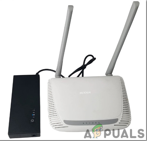
Backup Power Supply
How To Make A Portable Small Power Supply Unit?
Now as we know the abstract of the project, let us move forward and gather different information to start working. We will first make a list of the components and then assemble all the components together to make a working system.
Step 1: Collecting the Components
The best approach to start any project is to make a complete list of components. This is not only an intelligent way to start a project but it also saves us from many inconveniences in the middle of the project. A list of components, which are very easily available in the market, is given below:
- LEDs
- No products found.
- No products found.
- 12V Battery Holder Case
- Hot Glue Gun
- Digital MultiMeter
Step 2: Choosing The Main Components
The backbone of this project is the LiPO Battery that will provide the power to the circuit. LiPO battery is preferred in this project because of its long life and reliability. These batteries have a better current rating than other lithium battery types and are utilized in applications where weight is the most important feature that is taken into consideration while choosing the components. LiPo battery can give a backup of approximately 24 hours and even more than that. You can also charge your mobile phone up to 40% with this battery. The backup time can be calculated according to the current and voltage rating of the router. These batteries are used in media players, wireless Desktop Computer Peripherals, etc.
Step 3: Block Diagram
I have made a block diagram to understand the working principle of the circuit easily.
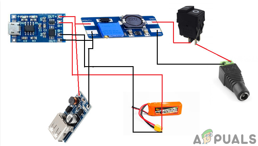
Block Diagram
Step 4: Understanding The Working Principle
After understanding the Block Diagram we will move towards the working principle of the circuit. The working principle of the circuit is very simple. The USB cable is used to draw the Power from the mains and it would be responsible for charging the LiPo Battery and it would also turn ON the router. When the load shedding occurs the LiPo battery would be able to operate the Router. It can be observed in the Block Diagram that the TP4056 charging module is connected to the LiPo battery and the output of the module is connected to the two boost converter modules. The first one is connected to the +12V Port of the router and the second one is connected to the socket of 5V for charging the Smartphone. We would set the Output Voltage of the Boost Converter Module by placing the Potentiometer on the PCB Board. We will rotate the knob of the potentiometer until it is set to 12V. You can adjust the voltage according to your router rating. The output from the boost converter would be connected to the DC jack through a Rocker push button.
Step 5: Preparing The Hardware
After understanding the working principle we will move on towards assembling the hardware components.
1. Making Some Alterations In The TP4056 Module.
The two LEDs are located on the charging module and they tell us the charging status of the battery. It is better to remove those LEDs and install the Breadboard LEDs so that we could monitor the status of the charging of the battery. I will desolder the LEDs that are placed on the module with the help of de-solder. Be careful while de-soldering the LEDs because if it is not done carefully the board could be damaged.
2. Soldering The Charging LEDs
The longer leg of the breadboard LED indicates the positive terminal and the shorter leg of the LED indicates the negative terminal. Now take the 24 gauge silicon wires and solder them with the legs of the LED. Apply hot glue on top of the terminals so that the wires may not be detached. Solder the terminal wires on the TP4056 module where the two original LEDs were placed.
3. Connecting The Battery Holder AndBoost Converters
Now we need to connect the battery holder to the TP4056 module. There are two +B and -B points on the charging module and they will be connected to the terminals of the battery holder. +B point will be connected to the positive terminal of the battery and the negative terminal of the battery will be connected to the -B point. Pick up the battery holder and solder it’s Red (positive) wire to the +B point and the Black (negative) wire to the -B point. Connect the Vin point of the boost converter to the Out+ point of the TP4056 module and connect the GND point of the boost converter to the Out- point of the TP4056 module.
4. Wiring The Jack And The Switch And Setting The Power Adapter
Solder two wires to the terminals of Rocker Push Button and the DC Jack. There are two legs of DC Jack and the smaller one represents the positive side. The larger one represents the negative side. Insert the components into a plastic casing and then connect the push button and Jack to the Boost Converter Module. Have a look at the router and check which size of Jack would be needed. The router would have all the specifications mentioned and you could easily decide whether which Jack needs to be connected. Look for the polarity on the router. In my case, the size of DC Jack is 5.5×2.1mm and the tip of polarity is positive.
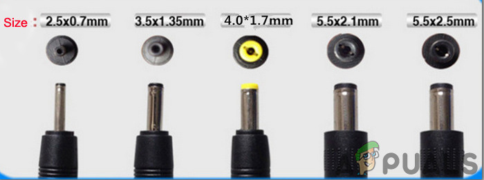
DC Jack Samples For Routers
Now, I will take two male DC Jacks and solder the tip of the positive jack to the smaller leg terminal and the negative tip to the larger leg of the terminal. Apply the hot glue on the terminals so that the wires may not detach from the terminals.
5. Finalizing The Hardware
We will assemble all of the components into the plastic casing and then insert the lipo battery into the holder. Handle the battery with great care because if you have connected the wronger polarity terminals, the battery could die forever. Now, we have assembled the hardware and all that needs to be done is testing. Before testing grabs a digital multi-meter and check the voltage of the battery, it should indicate 12V.
Step 6: Testing The Hardware And Giving Final Touches
Connect the device to the Lipo Battery Charger . Observe the two LEDs that are placed outside of the device. The RED LED indicates that the Lipo battery is in charging mode and when the battery is fully charged, Red LED turns OFF and the Green LED is turned ON . Now connect the wire that was altered before to the router and the Power Backup device that is designed by us. You will observe that the router is turned ON. We will check whether our USB port is working properly or not by connecting our mobile phone to that port. It would be observed that the mobile has gone into the charging mode.
That was all for today, Hope you would have enjoyed reading this article and after making your own backup for the router at home don’t forget to share your experience!
How to Fix “Printer is in an error state” Issue?
- Recognizing the importance of a printer’s duty cycle is crucial for choosing a device that matches your print volume needs. Staying within this limit ensures the printer operates efficiently and prolongs its lifespan, minimizing the risk of maintenance issues.
- Proper humidity, temperature, and cleanliness management can significantly enhance printer performance and maintain its duty cycle, preventing unnecessary wear.
- Enhancing a printer with upgrades like additional memory or better mechanical parts can improve its workload handling and extend its practical duty cycle, boosting overall durability and efficiency.
When choosing a new printer, you might come across the term “ duty cycle ” in the specifications. This guide will explain what a duty cycle is, why it matters, and how it can help you choose the right printer. We’ll keep things simple so you can easily understand how to use this information when shopping for a printer.
- Printer Duty Cycle: What It Means and Why It Matters?
- Why the Duty Cycle Is Key to Choosing the Right Printer?
- Duty Cycle vs. Recommended Monthly Print Volume: What’s the Difference?
- What Happens If You Ignore Printer Duty Cycle Recommendations? ↪ Real-World Scenarios: Why Exceeding the Duty Cycle Can Cost You
Printer Duty Cycle: What It Means and Why It Matters?

What is the meaning of Printer Duty Cycle?
The printer duty cycle represents the upper limit of a printer’s capacity—how many pages it can reliably process in a month before the risk of wear or malfunction increases. This figure is crucial for understanding printer performance limits and ensuring that your chosen printer can handle the expected work volume.
Manufacturers determine a printer’s duty cycle through stress testing, where the printer is pushed to its limit to identify how many pages it can produce each month before malfunctioning. These tests help set a reliable performance gateway for users.
A printer’s duty cycle is like a car’s speedometer—you wouldn’t drive a car at top speed all the time, and you shouldn’t push a printer to its maximum duty cycle. Doing so can lead to quicker wear and tear, more frequent maintenance, and a shorter lifespan.
If you’re unsure whether to choose an inkjet or laser printer, this detailed guide compares both options to help you make an informed decision.
Why the Duty Cycle Is Key to Choosing the Right Printer?

The Importance of Duty Cycle in printer selection
Knowing the duty cycle is essential when choosing a printer, as it determines how well the device can handle your monthly print volume without excessive wear or maintenance.
Here is why the duty cycle matters in printer selection:
- Fit for purpose: Selecting a printer with a suitable duty cycle ensures it can handle your monthly printing volume efficiently, reducing stress on its components.
- Longer lifespan and better performance: Staying within the duty cycle ensures optimal print quality and speed while prolonging the printer’s life, avoiding frequent breakdowns.
- Cost efficiency and reduced downtime: Operating within the duty cycle minimizes the need for repairs and reduces operational disruptions, managing long-term costs.
Duty Cycle vs. Recommended Monthly Print Volume: What’s the Difference?

Duty Cycle vs. recommended monthly print volume
The recommended monthly print volume is the optimal number of pages a printer should handle each month for the best performance and longevity. Unlike the maximum capacity indicated by the duty cycle, this number guides regular usage, ensuring the printer operates efficiently without excessive wear.
If your print volume regularly exceeds the recommended amount but stays within the duty cycle, the printer may operate safely in the short term, but it could still experience accelerated wear and reduced lifespan over time.
In such cases, consider upgrading to a higher-capacity printer or spreading print jobs across multiple devices to ensure long-term performance.
Here are the differences between the duty cycle and recommended monthly print volume:
- Duty cycle: Represents the maximum number of pages a printer can handle in a month without breaking down. It assesses the printer’s upper limit.
- Recommended monthly print volume: Suggests a practical, workable number of pages to print each month to keep the printer in good condition over its lifespan.
What Happens If You Ignore Printer Duty Cycle Recommendations?

Consequences of ignoring Duty Cycle recommendations |AndranikHakobyan via Canva
Ignoring the duty cycle limits poses more severe risks than exceeding the recommended monthly print volume, leading to serious long-term consequences.
While exceeding the recommended volume occasionally may result in additional wear and tear, consistently exceeding the duty cycle can lead to frequent breakdowns, reduced performance, and a shortened lifespan.
Ignoring duty cycle limits leads to frequent breakdowns, reduced performance, and increased maintenance, ultimately shortening the printer’s lifespan and causing more frequent operational downtime and higher repair costs. Long-term, pushing a printer beyond its limits leads to greater financial burdens due to premature replacements and inefficiencies.
↪ Real-World Scenarios: Why Exceeding the Duty Cycle Can Cost You
For example, in a busy law firm, overlooking duty cycle limits during a high-stakes period could cause a printer breakdown just before a critical deadline, delaying crucial legal filings and ultimately compromising client service.
For small businesses, consistently exceeding a printer’s duty cycle can lead to costly emergency repairs or premature equipment replacements, straining financial resources.
