In the recent century, Robotics is the most emerging field of research. Robots have taken control of almost everything that humans used to do. We can see autonomous robots performing various tasks in our society. There are some remote controlled Robots also that help us to carry out various operations. From making Nano circuits in the field of engineering to taking out complex surgeries in the field of medical, robots are more reliable than human beings.
Robotic Arm
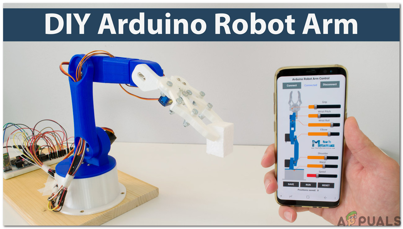
In this project, we are going to make a Robotic Arm that will be controlled by an Arduino microcontroller. It will be controlled via Bluetooth with the help of an android remote control app.
How To Control a Robotic Arm Using Arduino?
Now as we know the abstract of our project. Let us gather some more information about the circuitry and start building a Bluetooth controlled robotic arm and control it via Bluetooth.
Step 1: Collecting The Components
The best approach to start any project is to make a complete list of components. This is not only an intelligent way to start a project but it also saves us from many inconveniences in the middle of the project. A list of components of this project is given below:
- No products found.
- HC-05 Wireless Bluetooth Serial Transceiver
- No products found.
- 6V Adapter
- Jumper Wires
- Breadboard
Step 2: Studying The Components
As we have a complete list of all the components that we are going to use, let’s move a step ahead and go through a brief study of all the components.
Arduino Nano is a microcontroller board that carries out various operations in different circuits. It requires a C Code that tells the board what tasks to perform and how. It has 13 digital I/O pins which mean that we can operate 13 different devices. Arduino Nano has exactly the same functionality as Arduino Uno but in quite a small size. The microcontroller on the Arduino Nano board is ATmega328p. If you want to control more than 13 devices, use Arduino Mega.
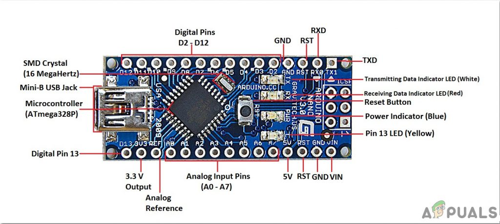
Arduino Nano
HC-05 Wireless Bluetooth Serial Transceiver : We need wireless communication in this project, so we will use Bluetooth technology and for that module that will be used is HC-05. This module has several programmable baud rates but the default baud rate is 9600 bps. It can be configured as either master or slave, whereas another module HC-06 can work only in slave mode. This module has four pins. One for VCC (5V) and the remaining three for GND, TX, and RX. The default password of this module is 1234 or 0000 . If we want to communicate between two microcontrollers or communicate with any device with Bluetooth functionality like a Phone or Laptop HC-05 helps us to do that. Several Android applications are already available which makes this process a lot easier.
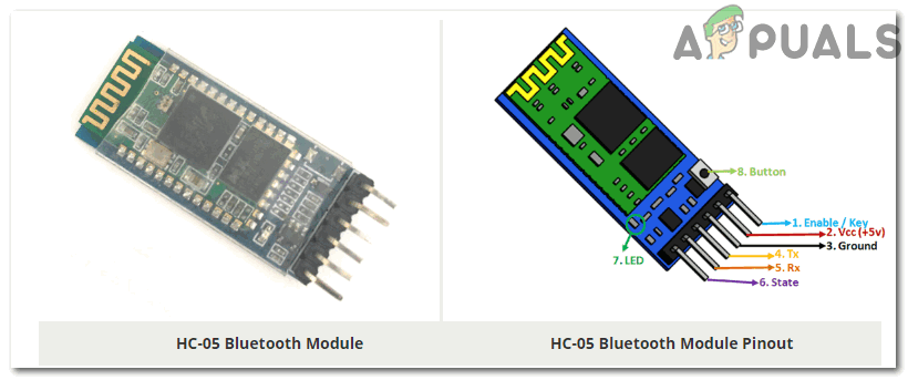
HC-05 Bluetooth Module
A typical Robotic Arm is made up of several segments and usually have 6 joints in it. It contains a minimum of 4 stepper motors which are controlled by the computer. Stepper motors are different from other DC motors. They move precisely in exact increments. These robotic arms are used to carry out various operations. We can operate them manually through a remote control or we can program them to work autonomously.
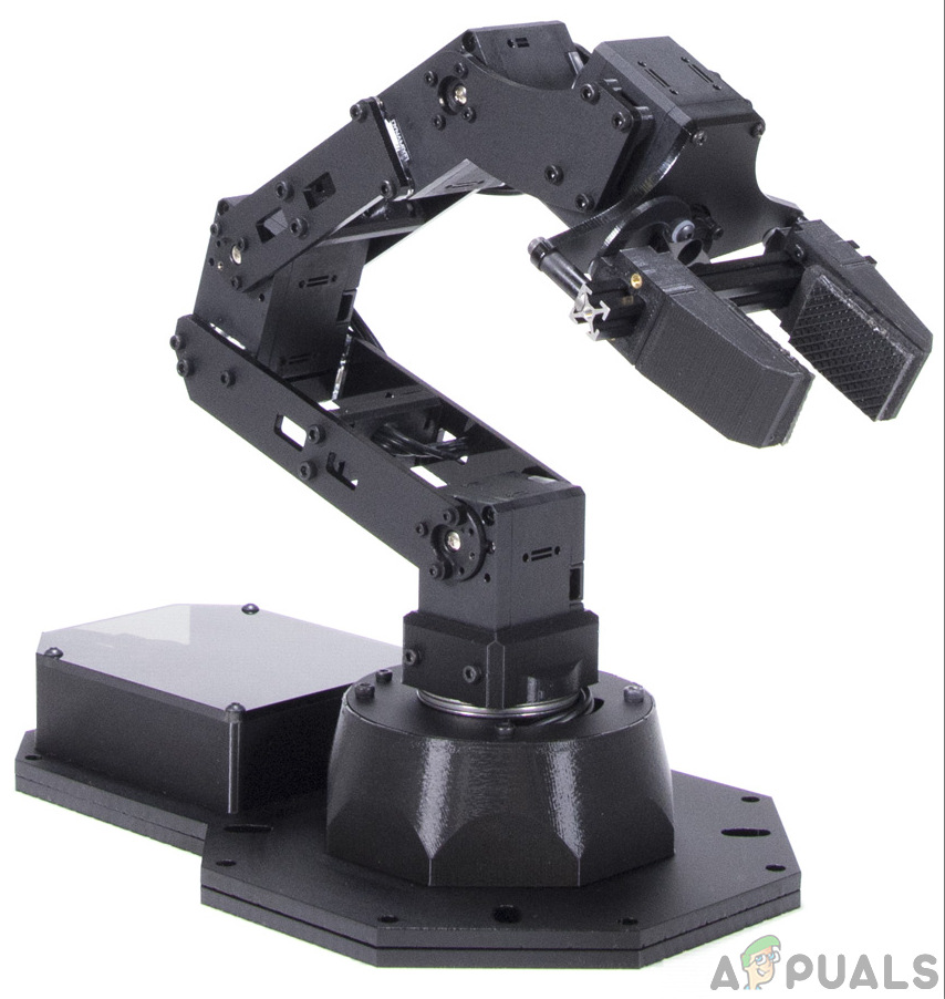
Robotic Arm.
Step 3: Assembling The Components
Now as we know about the working of all the main components used. Let’s start assembling them and make a circuit to build a remote-controlled robotic arm.
- .Attach the Arduino Nano board on the breadboard. The Arduino will be powered through the positive and negative wire of the adapter.
- Place the Bluetooth module on the breadboard too. Power up the Bluetooth module through Arduino. Connect the Tx pin of the Bluetooth module to the Rx pin of the Arduino Nan board and connect the Rx pin of the Bluetooth module to the Tx pin of the Arduino Nano board.
- As we know that there are 4 stepper motors. Each one has a technical name. They are called Elbow , Shoulder , Base, and Gripper . The Vcc and Ground of all the motors will be common and connected to the positive and negative of the 6V adapter. The Signal pin of all the four motors will be connected to pin5, pin6, pin9, and pin11 of Arduino Nano.
- Make sure that the connections you have made are according to the following circuit diagram. Circuit Diagram
Step 4: Getting Started With Arduino
If you are not already familiar with the Arduino IDE, don’t worry because a step by step procedure to set-up and use Arduino IDE with a microcontroller board is explained below.
- Download the latest version of Arduino IDE from Arduino.
- Connect your Arduino Nano board to your laptop and open the control panel. Then, click on Hardware and Sound . Now, click on Devices and Printers. Here, find the port to which your microcontroller board is connected. In my case it is COM14 but it is different on different computers. Finding Port
- Click on the Tool menu and set the board to Arduino Nano from the drop-down menu. Setting Board
- In the same Tool menu, set the port to the port number that you observed before in the Devices and Printers . Setting Port
- In the same Tool menu, Set the Processor to ATmega328P (Old Bootloader). Processor
- To write code to operate the servo motors, we need special library that will help us to write several functions for servo motors. This library is attached along with the code, in the link below. To include the library, click on Sketch > Include Library > Add ZIP. Library. Include Library
- Download the code attached below and paste it into your Arduino IDE. Click on the upload button to burn the code on your microcontroller board. Upload
Step 5: Downloading The App
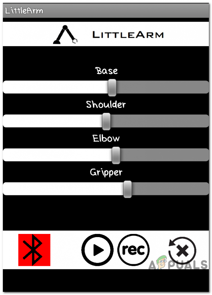
As we have now assembled the whole circuitry and uploaded the code in the microcontroller board. lets download a mobile app that will work as a remote control for the robotic arm. A free app is available on the google play store. The name of the app is the Little Arm Robot Control . To make a Bluetooth connection, turn on the Bluetooth on your mobile. Go to the settings and pair your mobile with the HC-05 module. After doing this, press the Bluetooth button in the app. If it turns green, it means that the app is now connected and ready to operate the robotic arm. There are sliders to set operate the robotic arm as desired.
App
Step 6: Understanding the Code
The code is well commented and easy to understand. Bur still, it is briefly explained below.
- In the start, A library is included to write a code to operate servo motors. Another library math.h is included to perform different mathematical operations in the code. Four objects are also initialized to be used for the four servo motors.
#include <Servo.h> //arduino library

#include <math.h> //standard c library


#define PI 3.141


Servo baseServo;

Servo shoulderServo;

Servo elbowServo;

Servo gripperServo;


int command;
- Then a structure is declared to take values for the base, shoulder, and elbow servo motors.
struct jointAngle{ // declairing a structure

int base;

int shoulder;

int elbow;

};
- After this, some variables are initialized to store the desired grip, delay, and position of the servo motor. the speed is set to be 15, and an object is made to take the value of the angle in the structure.
int desiredGrip;

int gripperPos;


int desiredDelay;


int servoSpeed = 15;

int ready = 0;


struct jointAngle desiredAngle; //desired angles of the servos
- void setup() is a function that is used to set the pins of Arduino as INPUT or OUTPUT. Here in this function, we have declared that the pin of the motors will be connected to which pins of the Arduino. It is also ensured that the Arduino doesn’t read serial input for too long. Initial Position and Baud Rate is also set in this function. Baud Rate is the speed by which the microcontroller board will communicate with the servos and Bluetooth module attached.
void setup()

{

Serial.begin(9600);

baseServo.attach(9); // attaches the base servo on pin 9 to the servo object

shoulderServo.attach(10); // attaches the shoulder servo on pin 9 to the servo object

elbowServo.attach(11);  // attaches the elbow servo on pin 9 to the servo object

gripperServo.attach(6);  // attaches the gripper servo on pin 9 to the servo object


Serial.setTimeout(50); //ensures the the arduino does not read serial for too long

Serial.println("started");

baseServo.write(90); //intial positions of servos

shoulderServo.write(150);

elbowServo.write(110);

ready = 0;

}
- servoParallelControl() is a function that is used to detect the current position of the robotic arm and move it according to the command given through the mobile app. If the current position is less than the actual, the arm will move up and vice versa. This function will return the value of the current position and the speed of the servo.
int servoParallelControl (int thePos, Servo theServo, int theSpeed ){


 int startPos = theServo.read(); //read the current pos

 int newPos = startPos;

 //int theSpeed = speed;


 //define where the pos is with respect to the command

 // if the current position is less that the actual move up

 if (startPos < (thePos-5)){

  newPos = newPos + 1;

  theServo.write(newPos);

  delay(theSpeed);

  return 0;

  }

  else if (newPos > (thePos + 5)){

   newPos = newPos - 1;

   theServo.write(newPos);

   delay(theSpeed);

   return 0;

   }

   else {

    return 1;

   }

}
- void loop() is a function that runs repeatedly in a loop. This function reads the data coming serially and store the angle of each servo in the structure. Initially, the status of all the servos is set to zero. Here a function servoParallelControl() is called and parameters are passed in it. this function will return the value and it will be stored in a variable of status.
void loop()

{

 if (Serial.available()){

 ready = 1;

 desiredAngle.base = Serial.parseInt();

 desiredAngle.shoulder = Serial.parseInt();

 desiredAngle.elbow = Serial.parseInt();

 desiredGrip = Serial.parseInt();

 desiredDelay = Serial.parseInt();


 if(Serial.read() == '\n'){


 Serial.flush(); //clear all other commands piled in the buffer

 //send completion of the command

 Serial.print('d');

 }

}


int status1 = 0;

int status2 = 0;

int status3 = 0;

int status4 = 0;

int done = 0 ;


while(done == 0 && ready == 1){

 //move the servo to the desired position

 status1 = servoParallelControl(desiredAngle.base, baseServo, desiredDelay);

 status2 = servoParallelControl(desiredAngle.shoulder, shoulderServo, desiredDelay);

 status3 = servoParallelControl(desiredAngle.elbow, elbowServo, desiredDelay);

 status4 = servoParallelControl(desiredGrip, gripperServo, desiredDelay);


  if (status1 == 1 & status2 == 1 & status3 == 1 & status4 == 1){

  done = 1

  }

 }// end of while

}
Now, this was the whole procedure of making a robotic arm. After burning the code and downloading the app, the robot should work perfectly fine when the sliders on the app are moved. You can also program the arm to work autonomously to perform the desired task.
How to Fix “Printer is in an error state” Issue?
- Recognizing the importance of a printer’s duty cycle is crucial for choosing a device that matches your print volume needs. Staying within this limit ensures the printer operates efficiently and prolongs its lifespan, minimizing the risk of maintenance issues.
- Proper humidity, temperature, and cleanliness management can significantly enhance printer performance and maintain its duty cycle, preventing unnecessary wear.
- Enhancing a printer with upgrades like additional memory or better mechanical parts can improve its workload handling and extend its practical duty cycle, boosting overall durability and efficiency.
When choosing a new printer, you might come across the term “ duty cycle ” in the specifications. This guide will explain what a duty cycle is, why it matters, and how it can help you choose the right printer. We’ll keep things simple so you can easily understand how to use this information when shopping for a printer.
- Printer Duty Cycle: What It Means and Why It Matters?
- Why the Duty Cycle Is Key to Choosing the Right Printer?
- Duty Cycle vs. Recommended Monthly Print Volume: What’s the Difference?
- What Happens If You Ignore Printer Duty Cycle Recommendations? ↪ Real-World Scenarios: Why Exceeding the Duty Cycle Can Cost You
Printer Duty Cycle: What It Means and Why It Matters?

What is the meaning of Printer Duty Cycle?
The printer duty cycle represents the upper limit of a printer’s capacity—how many pages it can reliably process in a month before the risk of wear or malfunction increases. This figure is crucial for understanding printer performance limits and ensuring that your chosen printer can handle the expected work volume.
Manufacturers determine a printer’s duty cycle through stress testing, where the printer is pushed to its limit to identify how many pages it can produce each month before malfunctioning. These tests help set a reliable performance gateway for users.
A printer’s duty cycle is like a car’s speedometer—you wouldn’t drive a car at top speed all the time, and you shouldn’t push a printer to its maximum duty cycle. Doing so can lead to quicker wear and tear, more frequent maintenance, and a shorter lifespan.
If you’re unsure whether to choose an inkjet or laser printer, this detailed guide compares both options to help you make an informed decision.
Why the Duty Cycle Is Key to Choosing the Right Printer?

The Importance of Duty Cycle in printer selection
Knowing the duty cycle is essential when choosing a printer, as it determines how well the device can handle your monthly print volume without excessive wear or maintenance.
Here is why the duty cycle matters in printer selection:
- Fit for purpose: Selecting a printer with a suitable duty cycle ensures it can handle your monthly printing volume efficiently, reducing stress on its components.
- Longer lifespan and better performance: Staying within the duty cycle ensures optimal print quality and speed while prolonging the printer’s life, avoiding frequent breakdowns.
- Cost efficiency and reduced downtime: Operating within the duty cycle minimizes the need for repairs and reduces operational disruptions, managing long-term costs.
Duty Cycle vs. Recommended Monthly Print Volume: What’s the Difference?

Duty Cycle vs. recommended monthly print volume
The recommended monthly print volume is the optimal number of pages a printer should handle each month for the best performance and longevity. Unlike the maximum capacity indicated by the duty cycle, this number guides regular usage, ensuring the printer operates efficiently without excessive wear.
If your print volume regularly exceeds the recommended amount but stays within the duty cycle, the printer may operate safely in the short term, but it could still experience accelerated wear and reduced lifespan over time.
In such cases, consider upgrading to a higher-capacity printer or spreading print jobs across multiple devices to ensure long-term performance.
Here are the differences between the duty cycle and recommended monthly print volume:
- Duty cycle: Represents the maximum number of pages a printer can handle in a month without breaking down. It assesses the printer’s upper limit.
- Recommended monthly print volume: Suggests a practical, workable number of pages to print each month to keep the printer in good condition over its lifespan.
What Happens If You Ignore Printer Duty Cycle Recommendations?

Consequences of ignoring Duty Cycle recommendations |AndranikHakobyan via Canva
Ignoring the duty cycle limits poses more severe risks than exceeding the recommended monthly print volume, leading to serious long-term consequences.
While exceeding the recommended volume occasionally may result in additional wear and tear, consistently exceeding the duty cycle can lead to frequent breakdowns, reduced performance, and a shortened lifespan.
Ignoring duty cycle limits leads to frequent breakdowns, reduced performance, and increased maintenance, ultimately shortening the printer’s lifespan and causing more frequent operational downtime and higher repair costs. Long-term, pushing a printer beyond its limits leads to greater financial burdens due to premature replacements and inefficiencies.
↪ Real-World Scenarios: Why Exceeding the Duty Cycle Can Cost You
For example, in a busy law firm, overlooking duty cycle limits during a high-stakes period could cause a printer breakdown just before a critical deadline, delaying crucial legal filings and ultimately compromising client service.
For small businesses, consistently exceeding a printer’s duty cycle can lead to costly emergency repairs or premature equipment replacements, straining financial resources.
