In the current century, everything is being shifted to WiFi. There are a lot of Weather stations available in the market that can are operated on WiFi and can be used in homes. These weather stations are connected to the internet and they include some sensors. Those stations sense the temperature, humidity or the pressure and display them on the screen that is already present in the gadget and sends the data to a mobile application through WiFi. These Sensors are very costly hence most people can’t afford them. We will make a weather station at home that will be efficient and economical too. It is very easy to make it at home by using components that are easily available in the market.

Weather Station
In this article, we are going to make a weather station using the ESP32 and BME280 sensors. The sensor will sense the respective parameter and send it to a web page through a local WiFi connection. For this, we will write code and burn it on the microcontroller board.
How To Make A Weather Station Using ESP32 and BME280?
As we now know the abstract of the project, let us move ahead and collect more information to start working on the project.
Step 1: Collecting The Components
The best approach to start any project is to make a list of components and going through a brief study of these components because no one will want to stick in the middle of a project just because of a missing component. A list of components that we are going to use in this project is given below:
- ESP32
- BME280
- No products found.
- No products found.
- No products found.
Step 2: Making A Table In HTML
Now let’s see how a table is made in HyperText Markup Language (HTML) and displayed in the web browser. HTML is a language used to create the structure of web pages. It consists of a series of elements that tell the browser how to display the things on the page. These elements are represented by tags. The browser reads the code written in HTML and renders the content on the screen without displaying the tags.
To create a table in the browser, we will use the
<table>
  <tr>
    <th>MEASUREMENT</th>
    <th>VALUE</th>
  </tr>
  <tr>
    <td>Temp. Celsius</td>
    <td>--- *C</td>
  </tr>
  <tr>
    <td>Temp. Fahrenheit</td>
    <td>--- *F</td>
  </tr>
  <tr>
    <td>Pressure</td>
    <td>--- hPa</td>
  </tr>
  <tr>
    <td>Approx. Altitude</td>
    <td>--- meters</td></tr>quantity that we are measuring the value of.
  <tr>
    <td>Humidity</td>
    <td>--- %</td>
  </tr>
</table>
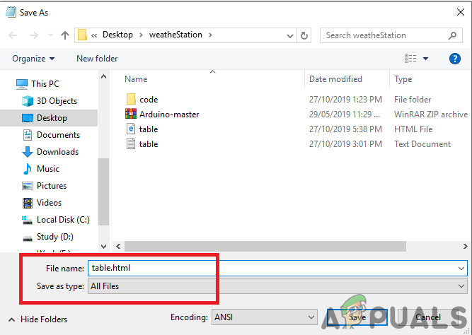
In the above code, two cells of the first columns are named as Measurement and Value. Below this, six rows are created and each is for the different quantity that is to be measured. Write this code on notepad. Click on the File menu in the upper top- left corner of the screen. Click on Save As and name your file with an extension of .html. Now change the Save As Type to ALL. Click on the save button to save the file. A browser will be created in the folder where that text file is placed. Click on that file to view your table in the browser.
Save As

Table
Step 3: Assembling The Components
Now let us move ahead and connect the sensor to the ESP32 board. Before making these connections, It is better to go through a brief study of the configuration of the pins of the Sensor.
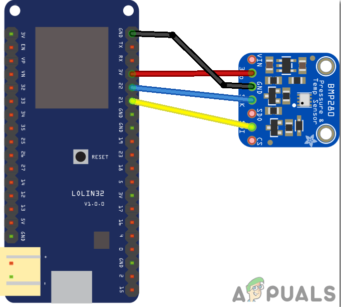
A BME280 sensor has seven pins on it. One Pin is the Vcc pin that is used to power up the sensor and the second in is a ground pin. The input supply that is applied to the Vcc pin must be in the range of 1.8V to 3.6V. The I 2 C Serial data transmission (bi-directional) can be achieved by the SDA and SCL pin. SCK is used for the clock line in the transmission process. SDO pin is used for the data coming out of the BME280 sensor. SDI pin is used for the data going out of the BME280 sensor. The active-low chip selected is the CS pin.
The protocol that we are going to use in this project is 12C communication with the BME280 sensor module. For this purpose, we are going to use the SDA and SCL pin of the sensor. Connect pin21 of the ESP32 is connected to the SDA pin of the sensor and the pin22 of the ESP32 is connected to the SCL f the sensor.
When all the connections are made, connect the microcontroller board to the computer and burn the code in it. Press the Enable button to start it. The connections of the diagram will look like:
Connections
Step 4: Getting Started With ESP32
If you haven’t worked on Arduino IDE before, don’t worry because a step by step to set up Arduino IDE is shown below.
- Download the latest version of Arduino IDE from Arduino.
- Connect your Arduino board to the PC and open Control Panel. Click on Hardware and Sound. Now open Devices and Printer and find the port to which your board is connected. In my case it is COM14 but it is different in different computers. Finding Port
- Click on File and then click on Preferences. Copy the following link in the Additional Board Manager’s URL. “ https://dl.espressif.com/dl/package_esp32_index.json” Preferences
- Now, to use ESP32 with Arduino IDE, we need to import special libraries that will allow us to burn code on ESP32 and use it. these two libraries are attached in the link given below. To include the library, goto Sketch > Include Library > Add ZIP Library . A box will appear. Find the ZIP folder on your computer and click OK to include the folders. This library is attached along with the code in the link below. Include Library
- Now goto Sketch > Include Library > Manage Libraries. Manage Libraries
- A Menu will be opened. In the Search bar, type adafruit bme280. This package will be used to integrate the BME280 sensor and take readings from it. The package will appear on the screen. Install the package by clicking on the install button. Installing Package
- In the same Library Manager, search for Adafruit Unified Sensor. This library also helps the BME280 sensor to be used with ESP32. A list will appear in the box. Go to the end of the list and select the library that is shown in the image below. Click on the install button to install the library. Installing Library
- A Menu will open. In the search bar, type Arduino JSON. A list will appear. Install Arduino JSON by Benoit Blanchon. Arduino JSON
- Now click on the Tools. A dropdown menu will appear. Set the board to ESP Dev Module. Setting Board
- Click on the Tool menu again and set the port that you observed in the control panel before. Setting Port
- Now Upload the code that is attached in the link below and click on the upload button to burn the code on the ESP32 microcontroller. Upload
So now when you will upload the code, an error may occur. This is the most common error that may occur if you are using a new version of the Arduino IDE and the Arduino JSON. The following are the errors that you may see on the screen.
In file included from C:\Users\Pro\Documents\Arduino\libraries\IOXhop_FirebaseESP32-master/IOXhop_FirebaseESP32.h:8:0, from C:\Users\Pro\Desktop\smartHome\code\code.ino:2: C:\Users\Pro\Documents\Arduino\libraries\IOXhop_FirebaseESP32-master/IOXhop_FirebaseStream.h:14:11: error: StaticJsonBuffer is a class from ArduinoJson 5. Please see arduinojson.org/upgrade to learn how to upgrade your program to ArduinoJson version 6 StaticJsonBuffer jsonBuffer; ^ In file included from C:\Users\Pro\Documents\Arduino\libraries\IOXhop_FirebaseESP32-master/IOXhop_FirebaseESP32.h:8:0, from C:\Users\Pro\Desktop\smartHome\code\code.ino:2: C:\Users\Pro\Documents\Arduino\libraries\IOXhop_FirebaseESP32-master/IOXhop_FirebaseStream.h:65:11: error: StaticJsonBuffer is a class from ArduinoJson 5. Please see arduinojson.org/upgrade to learn how to upgrade your program to ArduinoJson version 6 return StaticJsonBuffer().parseObject(_data); ^ Multiple libraries were found for “WiFi.h” Used: C:\Users\Pro\AppData\Local\Arduino15\packages\esp32\hardware\esp32\1.0.2\libraries\WiFi Not used: C:\Program Files (x86)\Arduino\libraries\WiFi Using library WiFi at version 1.0 in folder: C:\Users\Pro\AppData\Local\Arduino15\packages\esp32\hardware\esp32\1.0.2\libraries\WiFi Using library IOXhop_FirebaseESP32-master in folder: C:\Users\Pro\Documents\Arduino\libraries\IOXhop_FirebaseESP32-master (legacy) Using library HTTPClient at version 1.2 in folder: C:\Users\Pro\AppData\Local\Arduino15\packages\esp32\hardware\esp32\1.0.2\libraries\HTTPClient Using library WiFiClientSecure at version 1.0 in folder: C:\Users\Pro\AppData\Local\Arduino15\packages\esp32\hardware\esp32\1.0.2\libraries\WiFiClientSecure Using library ArduinoJson at version 6.12.0 in folder: C:\Users\Pro\Documents\Arduino\libraries\ArduinoJson exit status 1 Error compiling for board ESP32 Dev Module.
There is nothing to worry about because we can eliminate these errors by following some simple steps. These errors are arising because the new version of Arduino JSON has another class instead of StaticJsonBuffer. This is the class of JSON 5. So, we can simply eliminate this error by downgrading the version of Arduino JSON of our Arduino IDE. Simply go to Sketch > Include Library > Manage Libraries. Search for Arduino JSON by Benoit Blanchon that you have installed before. Uninstall it first and then set its version to 5.13.5. Now as we have set an old version of Arduino JSON, install it again and recompile the code. This time, your code will compile successfully.
Step 5: Understanding The Code
The code of this project is very simple and well commented. But still, the code is briefly explained below.
- In the start, libraries are included so that the ESP32 board can be connected to the local WiFi connection in the home or office. The libraries that help the ESP32 to integrate the BME280 sensor with it, are also included. Then the name and password of your local wifi connection are defined so that the ESP32 could be connected to the Wifi.
// Load Wi-Fi library
#include <WiFi.h>            // libray to use wifi
#include <Wire.h>
#include <Adafruit_BME280.h> // library to use BME280 sensor
#include <Adafruit_Sensor.h> // library to use BME280 sensor
- After this, some lines are commented on. Thes lines will be used if you are using SPI protocol for the communication of the sensor. We will keep them commented because we are using the 12C protocol.
/*#include <SPI.h>
#define BME_SCK 18
#define BME_MISO 19
#define BME_MOSI 23
#define BME_CS 5*/
- A variable is created to save the value of the sea level pressure in hectopascal. 1 hectopascal is equivalent to a millibar. The altitude for the given pressure is estimated and then this variable compares it with the sea level pressure. After this, bme is an object that is created for further use.
#define SEALEVELPRESSURE_HPA (1013.25)  // variable to compare found pressure to sea level

Adafruit_BME280 bme;                    // I2C
- After this, the name of your WiFi connection and its power is included n the code, so that the ESP32 can be connected to the WiFi. Then after this, the port number is set to communicate with the webserver and a variable is declared to store the HTTP request.
const char* ssid = "YOUR SSID";            // Name of your local wifi connection
const char* password = "YOUR PASSWORD";    // Password of your local wifi connection
WiFiServer server(80);                     // Set web server port number to 80
String header;                             // Variable to store the HTTP request
- void setup() is a function in which we initialize the INPUT or OUTPUT pins. This function also sets the baud rate by using Serial.begin() command. Baud Rate is the communication speed of the microcontroller. Some lines of code are added here to connect the ESP32 to the local wifi connection. The board will try to connect to the local wifi connection and will print “connection.” in the serial monitor. It will print “Connected” when the connection is established. So to monitor this, it is better to open the serial monitor and check its staus there.
void setup() {
Serial.begin(115200);                             // setting the baud rate
bool status;

// default settings
// (you can also pass in a Wire library object like &Wire2)
//status = bme.begin();
if (!bme.begin(0x76)) {                           // checking if sensor is fouund
Serial.println("Could not find a valid BME280 sensor, check wiring!");
while (1);
}

// Connect to Wi-Fi network with SSID and password
Serial.print("Connecting to ");
Serial.println(ssid);
WiFi.begin(ssid, password);
while (WiFi.status() != WL_CONNECTED) {
delay(500);
Serial.print(".");
}

// Print local IP address and start web server
Serial.println("");
Serial.println("WiFi connected.");
Serial.println("IP address: ");              //  print the ip address on serial monitor
Serial.println(WiFi.localIP());
server.begin();
}
- void loop() is a function which runs repeatedly in a loop. In this loop, we write a code that tells the microcontroller board what tasks to carry out and how. In this code, first, a connection is established with a new client. If the connection is established, the web page is displayed on the browser. Then the table is made and the sensors readings are filled in that table. When the table is filled, the connection gets closed.
void loop(){
 WiFiClient client = server.available(); // Listen for incoming clients

 if (client) {                                       // If a new client connects,
  Serial.println("New Client.");                     // print a message out in the serial port
  String currentLine = "";                           // make a String to hold incoming data from the client
  while (client.connected()) {                       // loop while the client's connected
  if (client.available()) {                          // if there's bytes to read from the client,
   char c = client.read();                           // read a byte, then
   Serial.write(c);                                  // print it out the serial monitor
   header += c;
   if (c == '\n') {                                  // if the byte is a newline character
    // if the current line is blank, you got two newline characters in a row.
    // that's the end of the client HTTP request, so send a response:
    if (currentLine.length() == 0) {
     // HTTP headers always start with a response code (e.g. HTTP/1.1 200 OK)
     // and a content-type so the client knows what's coming, then a blank line:
     client.println("HTTP/1.1 200 OK");
     client.println("Content-type:text/html");
     client.println("Connection: close");
     client.println();

     // Display the HTML web page
     client.println("<!DOCTYPE html><html>");
     client.println("<head><meta name=\"viewport\" content=\"width=device-width, initial-scale=1\">");
     client.println("<link rel=\"icon\" href=\"data:,\">");
     // CSS to style the table
     client.println("<style>body { text-align: center; font-family: \"Trebuchet MS\", Arial;}");
     client.println("table { border-collapse: collapse; width:35%; margin-left:auto; margin-right:auto; }");
     client.println("th { padding: 12px; background-color: #0043af; color: white; }");
     client.println("tr { border: 1px solid #ddd; padding: 12px; }");
     client.println("tr:hover { background-color: #bcbcbc; }");
     client.println("td { border: none; padding: 12px; }");
     client.println(".sensor { color:white; font-weight: bold; background-color: #bcbcbc; padding: 1px; }");

     // Web Page Heading
     client.println("</style></head><body><h1>ESP32 with BME280</h1>");
     client.println("<table><tr><th>MEASUREMENT</th><th>VALUE</th></tr>");
     client.println("<tr><td>Temp. Celsius</td><td><span class=\"sensor\">");
     client.println(bme.readTemperature());
     client.println(" *C</span></td></tr>");
     client.println("<tr><td>Temp. Fahrenheit</td><td><span class=\"sensor\">");
     client.println(1.8 * bme.readTemperature() + 32);
     client.println(" *F</span></td></tr>");
     client.println("<tr><td>Pressure</td><td><span class=\"sensor\">");
     client.println(bme.readPressure() / 100.0F);
     client.println(" hPa</span></td></tr>");
     client.println("<tr><td>Approx. Altitude</td><td><span class=\"sensor\">");
     client.println(bme.readAltitude(SEALEVELPRESSURE_HPA));
     client.println(" m</span></td></tr>");
     client.println("<tr><td>Humidity</td><td><span class=\"sensor\">");
     client.println(bme.readHumidity());
     client.println(" %</span></td></tr>");
     client.println("</body></html>");

     // The HTTP response ends with another blank line
     client.println();
     // Break out of the while loop
     break;
     }
     else { // if you got a newline, then clear currentLine
      currentLine = "";
     }
    }
    else if (c != '\r') { // if you got anything else but a carriage return character,
     currentLine += c; // add it to the end of the currentLine
    }
   }
  }
 // Clear the header variable
 header = "";
 // Close the connection
 client.stop();
 Serial.println("Client disconnected.");
 Serial.println("");
 }
}
This was the whole procedure of how to make a weather station using ESP32, now after collecting the hardware components from the market and start making your own. Good Luck!
How to Fix “Printer is in an error state” Issue?
- Recognizing the importance of a printer’s duty cycle is crucial for choosing a device that matches your print volume needs. Staying within this limit ensures the printer operates efficiently and prolongs its lifespan, minimizing the risk of maintenance issues.
- Proper humidity, temperature, and cleanliness management can significantly enhance printer performance and maintain its duty cycle, preventing unnecessary wear.
- Enhancing a printer with upgrades like additional memory or better mechanical parts can improve its workload handling and extend its practical duty cycle, boosting overall durability and efficiency.
When choosing a new printer, you might come across the term “ duty cycle ” in the specifications. This guide will explain what a duty cycle is, why it matters, and how it can help you choose the right printer. We’ll keep things simple so you can easily understand how to use this information when shopping for a printer.
- Printer Duty Cycle: What It Means and Why It Matters?
- Why the Duty Cycle Is Key to Choosing the Right Printer?
- Duty Cycle vs. Recommended Monthly Print Volume: What’s the Difference?
- What Happens If You Ignore Printer Duty Cycle Recommendations? ↪ Real-World Scenarios: Why Exceeding the Duty Cycle Can Cost You
Printer Duty Cycle: What It Means and Why It Matters?

What is the meaning of Printer Duty Cycle?
The printer duty cycle represents the upper limit of a printer’s capacity—how many pages it can reliably process in a month before the risk of wear or malfunction increases. This figure is crucial for understanding printer performance limits and ensuring that your chosen printer can handle the expected work volume.
Manufacturers determine a printer’s duty cycle through stress testing, where the printer is pushed to its limit to identify how many pages it can produce each month before malfunctioning. These tests help set a reliable performance gateway for users.
A printer’s duty cycle is like a car’s speedometer—you wouldn’t drive a car at top speed all the time, and you shouldn’t push a printer to its maximum duty cycle. Doing so can lead to quicker wear and tear, more frequent maintenance, and a shorter lifespan.
If you’re unsure whether to choose an inkjet or laser printer, this detailed guide compares both options to help you make an informed decision.
Why the Duty Cycle Is Key to Choosing the Right Printer?

The Importance of Duty Cycle in printer selection
Knowing the duty cycle is essential when choosing a printer, as it determines how well the device can handle your monthly print volume without excessive wear or maintenance.
Here is why the duty cycle matters in printer selection:
- Fit for purpose: Selecting a printer with a suitable duty cycle ensures it can handle your monthly printing volume efficiently, reducing stress on its components.
- Longer lifespan and better performance: Staying within the duty cycle ensures optimal print quality and speed while prolonging the printer’s life, avoiding frequent breakdowns.
- Cost efficiency and reduced downtime: Operating within the duty cycle minimizes the need for repairs and reduces operational disruptions, managing long-term costs.
Duty Cycle vs. Recommended Monthly Print Volume: What’s the Difference?

Duty Cycle vs. recommended monthly print volume
The recommended monthly print volume is the optimal number of pages a printer should handle each month for the best performance and longevity. Unlike the maximum capacity indicated by the duty cycle, this number guides regular usage, ensuring the printer operates efficiently without excessive wear.
If your print volume regularly exceeds the recommended amount but stays within the duty cycle, the printer may operate safely in the short term, but it could still experience accelerated wear and reduced lifespan over time.
In such cases, consider upgrading to a higher-capacity printer or spreading print jobs across multiple devices to ensure long-term performance.
Here are the differences between the duty cycle and recommended monthly print volume:
- Duty cycle: Represents the maximum number of pages a printer can handle in a month without breaking down. It assesses the printer’s upper limit.
- Recommended monthly print volume: Suggests a practical, workable number of pages to print each month to keep the printer in good condition over its lifespan.
What Happens If You Ignore Printer Duty Cycle Recommendations?

Consequences of ignoring Duty Cycle recommendations |AndranikHakobyan via Canva
Ignoring the duty cycle limits poses more severe risks than exceeding the recommended monthly print volume, leading to serious long-term consequences.
While exceeding the recommended volume occasionally may result in additional wear and tear, consistently exceeding the duty cycle can lead to frequent breakdowns, reduced performance, and a shortened lifespan.
Ignoring duty cycle limits leads to frequent breakdowns, reduced performance, and increased maintenance, ultimately shortening the printer’s lifespan and causing more frequent operational downtime and higher repair costs. Long-term, pushing a printer beyond its limits leads to greater financial burdens due to premature replacements and inefficiencies.
↪ Real-World Scenarios: Why Exceeding the Duty Cycle Can Cost You
For example, in a busy law firm, overlooking duty cycle limits during a high-stakes period could cause a printer breakdown just before a critical deadline, delaying crucial legal filings and ultimately compromising client service.
For small businesses, consistently exceeding a printer’s duty cycle can lead to costly emergency repairs or premature equipment replacements, straining financial resources.
